Friday 2 September 2016

Stucture analysis of rigid body

hello friends...I hope all of you are fine. In my previous blog related to modeling and steady state thermal simulation of cylinder head fin I had demonstrated that how we can perform thermal analysis of any object. For this we should require a practical data of materials, load acting on it, environmental conditions, good software knowledge and some deep knowledge of  meshing. All above things bring us a powerful result. Practical labs in previous days occupy their special status in any R & D departments in the industries but now a day, any CAD/CAE software and computers take this positions. For fast and strong result oriented design validation, we require a good a good skills in CAD/ CAE. You can use any one software like Cre-O, Pro-E, ANSYS, solid works, AutoCAD, NX etc. It is not necessary that you require skills of all software, but should fluency in any one design software and any one CAE software. AutoCAD, NX and CreO  are used in industries as CAD software and ANSYS and NX are used as FEA(finite element analysis). I use ANSYS and NX in preparation of this blog. You can use AutoCAD or some another CAD software in place of NX but for better FEA result, you should use ANSYS.
In this blog I will demonstrate you how to perform a structural simulation in ANSYS.
Go to Start menu and select Workbench 15.0 and click OK
Start>Workbench15.0>ok
Now ANSYS toolbox appears in left portion of your computer screen. Select Structural and double click on it. Your new project is starting in ANSYS. Right click on the box and rename it as Fixed support analysis.
Here tick mark appear in material box. it indicates that default material Structural steel if loaded in project. Right click on Geometry and click new geometry. Design modeler will starting in few seconds
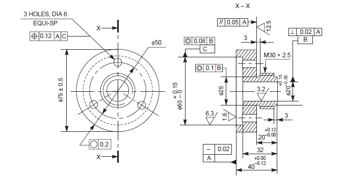
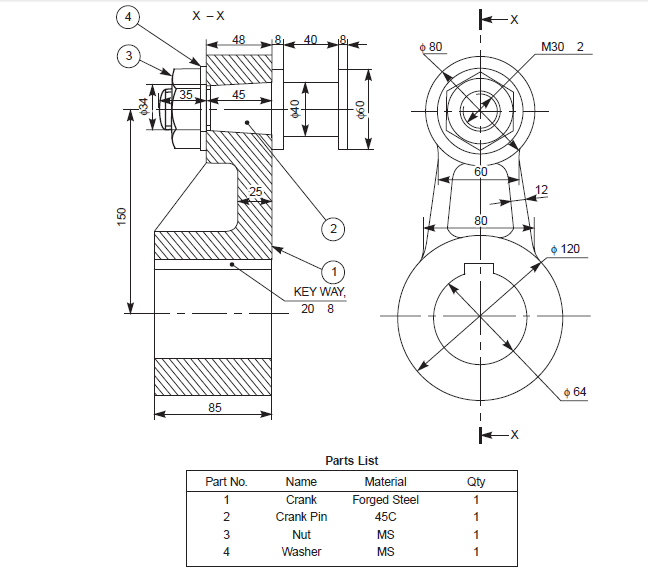
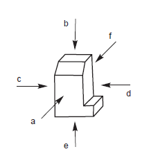
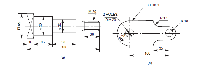
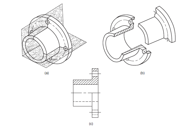
Now construct a geometry as per following model and dimensions. You can take your own dimensions but model which u have design must be appears like this


model geometry
 
Here I will not display ant dimensions, You can take your own "practicable" dimensions. Your model is ready in design modeler and now you can close design modeler and ansys automatically save your model. Now right click omn model and select Edit....mechanical APDL will starting soon. You can see in lower left portion of the screen as " starting mechanical"
New window of ANSYS mechanical is appears and setup mesh, load and geometric constrain in the model

Mesh
 create a fine mesh of the model. I take element size as 1 mm and you can also modify your model mesh parameters which are appears in lower left portion of screen. Expand sizing option and adjust mesh settings. your mesh geometry will appears like following figure.
Mesh geometry
Fixed Support
Now we will apply a fixed support at both holes appearing in the model. Right click on structural analysis and select insert and then select fixed geometry and click apply in dialog box. Your model will shown as follows.
Fixed supports
Applying Force
Now we require a force applying on model. Right click on structural analysis and select insert and than select force. Select a upper face of the support. Give amount of force and select component in the right direction. another two or one component should free. Direction of force will appear in graphic area. Your model will appear as follows.
Applying Force

Analysis Results
Now its time to solve the problem and make analysis of result. Right click on structural analysis and click on solve. ANSYS take few time to solve the problem. If your meshing is very fine and element size is small, than it will take longer time.
Once your solution is completed than insert solution data like stress, strain, energy, deformation, equivalent stress etc.
Here in included following result plots in my simulation result. you can use another plots as per your requirements
  1. equivalent stress
  2. strain energy
  3. shear stress
  4. total deformation
  5. factor of safety
Equivalent Stress
Equivalent stress
here we can see than maximum stress generated at inner portion of hole and minimum stress generated at handle portion of model. We can also make animation video as per time and frame in which we like to play
Total deformation
Total deformation
Total deformation results we can also assume from common sense that fixed portion will deform very or no and handle portion will deform large. This result we can see in above total deformation plot.
Shear stress
Common engineering assumption is that where hole portions are in machine components, there must be high shearing. We know this from our engineering study, but here we can also see that fixed hole has highest shearing and another part of model has low shearing stress
Shear stress

Strain Energy
Strain energy distribution as follows. High value of strain energy appears at joint portions of the model.
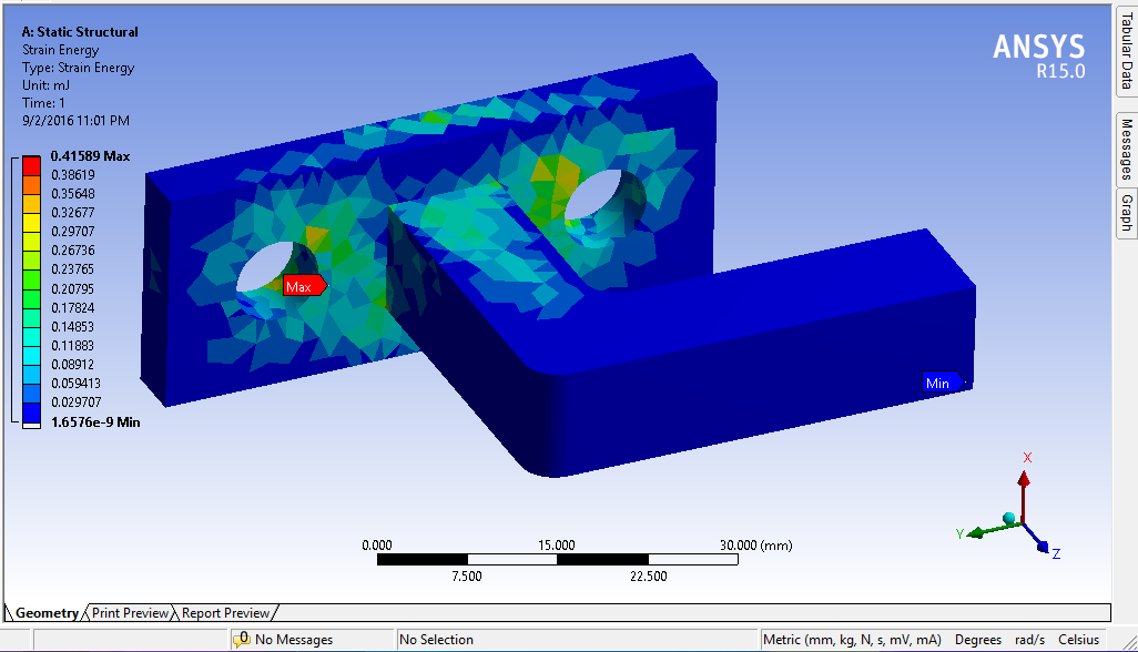
Strain energy
Factor of Safety
For true design and validation, FOS plot is very important for designer to take any decision. This plot will shows us that how FOS distributed in model. Definition of FOS is up to us.
Factor of Safety
Thanks foe reading my blog........
Any further help u van contact me

Tuesday 30 August 2016

Basics of Engineering Drawing

hello friends......how are you? hope you all are fine and enjoy the rainy season. This season is too good for traveling in some hill stations. All people will go to hill stations in summer but as per my opinion, this season is more suitable to visit any hill station. Specially for people who are living in Gujarat, I suggest them to visit Saputara or Giranar in this time. Mahabaleshwar is also good option. Their trip may lifelong unforgotten.....Now I come to my next blog...Hope you enjoy it...... 
This blog is about basic knowledge of engineering drawing. Most of engineering students have learn this subject in their first year of engineering. I had also learn Engineering Graphics in first semester in my college. This was my first lecture in engineering field and I had newer thought that I will writing blogs about engineering drawing....Basic ideas about engineering graphics or drawing is very important in professional life of any Engineer. As we know Engineering drawing is the language of engineer. Ant two engineer in the world may never understood their language but they can easily understand the drawing prepared by another engineer. So engineering drawing is very important. If engineer can't understand the drawing and make any wrong decision about design, production etc. than it may very dangerous for their organization and people who are using that products.
Some types of engineering drawing are as follows
  1. Machine drawing
  2. Production drawing  
  3. Assembly drawing
  4. Exploded assembly drawing
Machine drawing is most popular type of engineering drawing. It have different orthographic vies and dimensions of component. normally in machine drawing there are only one component in the drawing and different views of that component are drawn. Section views and half section views are also include in the drawing. Some components may require to four vies or may all six vies for complete understanding. i.e. bike engine cylinder of DTS-i technology.
Figure-1 Machine drawing

 Production drawing is also referred as working drawing. Production drawing must includes all dimensions, limits and tolerances, special finishing processes like honing, heat treatment, lapping, surface finish. etc. Title of different parts and material used in that parts also be included in the drawing for craftsman understanding. Normally craftsman prepare one component at a time so it is advised to prepare separate drawing of each components. If related component drawing is necessary than it may be provided as extra.

Figure 2- Production Drawing


 Assembly drawing includes all the connecting parts in one single drawing.All parts must their correct working positions and drawing also includes a material box. Material box provide an information for different materials of different parts and number of quantity of that particular part.
Figure 3- Assembly Drawing
Exploded assembly drawing has exploded pictorial views are supplied to meet instruction manual requirements.

These drawings generally find a place in the parts list section of a company instruction manual.  experience in the reading of drawings; because in these exploded views, the parts are positioned in the sequence of assembly, but separated from each other.


Figure-4 Exploded assembly view


Title Block

Title block included in the lower right portion of the drawiung sheet. Maximum length of the title block is 170mm and ti includes following 
informations
  • Title of the drawing
  • Sheet number
  • Scale
  • Symbol of projection
  • Name of firm
  • Initial of staff drawn, checked and approved
 
According to Bureau of Indian Standards, SP-46:1998, ‘‘Engineering Drawing Practice 
for Schools and Colleges’’, First angle projection is preferred


Figure-5 Title block


Drawing sheet layout is as follows


Figure 6-Drawing sheet laout


Four centering marks may be provided, in order to facilitate positioning of the drawing. Two orientation mark may be provided to indicate the orientation of the drawing sheet on the drawing board.


It is recommended to provide a figure-less metric reference graduation, with a minimum length 
of 100 mm and divided into 10 intervals on all the drawing sheets which are intended 
to be microfilmed. The metric reference graduation may be disposed symmetrically about a 
centering mark, near the frame at the border, with a minimum width of 5 mm


Scale

Scale is the ratio of the linear dimension of an element of an object as represented in the  
drawing, to the real linear dimension of the same element of the object itself. Wherever possible, 

it is desirable to make full size drawings, so as to represent true shapes and sizes. If this is not 

practicable, the largest possible scale should be used. While drawing very small objects, such 

as watch components and other similar objects, it is advisable to use enlarging scales.


SCALE 1 : 1 for full size,
SCALE × : 1 for enlarged scales,
SCALE 1 : × for reduced scales

Lines


Lines of different types and thicknesses are used for graphical representation of objects.


Figure 7-Types of lines
Application of lines

Above lines are used in drawing as indicated in following figure
Figure-8 Applications of lines


Order of priority of coincided lines
When two or more lines are coincided than it is important task for engineer to give priority of drawing lines
 
  1. Visible outline and edges
  2. Hidden outline and edges
  3. Cutting planes
  4. Center lines and line of symmetry
  5. centroid lines
  6. Projection lines


Figure-9 Order of priority of lines


 Conventional representation of materials
Engineeering drawing include so many different types of materials and for reading the engineeniring drawing, wee must have different representation of these materials. Steel, metals, wood, liquid, concrete etc. have its special symbols of representations


Figure-10 Conventional representation of materials
 Conventional representation of machine components

When drawing include repetition of same thing than it is advised to make conventional representation of the drawing. This way may save time of drawing. Some examples are as follows


Figure 11- Conventional representation of machine component
Dimension Principles
 
Drawing is finished after providing a proper dimensions in a specific unit system. It helps engineer to read the drawing. It represented by numeric value by thin lines, symbols etc.
  • As far as possible, dimensions should be placed outside from the drawing
  • Dimension should be taken from visible outline rather than invisible outline
  • Dimensioning of center line should be avoided except when the center line passes from center of the hole
  • Each feature should dimensioned once only in the drawing
  •  Dimension should be placed on the view or section that relates to the corresponding feature
  • Each drawing should use same unit for all dimensions
  • No more dimensions than are necessary to define a part
  • No feature of a part should be defined by more than one dimension in any one direction
Orthographic view

Figure 12- Orthographic view
Figure 13- (a) First angle (b) Third angle

Applications of hidden lines
While make drawing of some component and make projection of it may seen that some parts are not visible. For representation of these parts, hidden lines are used.


Figure-14 Hidden lines
 

Curved surfaces
 
Difficulty in representing the surface can be overcome by following some rules. Whenever the tangential line of curved surface becomes in the projector, a line should be drawn from adjacent view.
 

Figure -15 Curved surfaces


One view drawing
Some machine components are symmetrical about two axis and than we only require one view of this type of component and we can easily drawn a 3D component by using this drawing 
Figure-16 One view drawing
Section and half section views

Section view is representation of cut component in drawing. A section line indicates that object cut portion and view of cut component may be sheen in following example


Figure-17 Section view representation

Figure -18 Half section view representation


thanks for reading this. I hope you people learn something from this and may be useful for drafting techniques in industrial areas........thanks again....

Contact:
www.andromedacad@gmail.com 
+91 8758951337


Sunday 28 August 2016

Modeling and Steady state thermal analysis of cylinder head with fins

hello friend....Hope you all are well and good. Here i come up with my new blog relating to modeling of cylinder with fin arrangement in NX 10.0 and Steady state thermal analysis in ANSYS 15.0. Hope You People enjoy it..... 
  • Step :1 Preparation of model in NX10.0  

First of all  Prepare a 3D model in NX as per following data. You can use your own data and prepare your own model but it may cause change in simulation result and so many differences in final analysis. You can also use another modeling software like Solid works, Auto cad, Catia, Pro-E etc. Dimensions are as follows 

Figure 1: Drafting of Cylinder fin


 After doing sketching exercise you need to convert your drawing into 3D part . After creating 3D model your model like this.... 

Figure 2: 3D modeling of Cylinder fin

After complete modeling, you have to save your part in your PC in .igs or .step formats....save it in .igs file
  • Step:2 Importing CAD model in ANSYS

Go to start>Workbench 15.0 and wait for starting ANSYS. Now select Steady State Thermal in the left portion of your ANSYS 
Now select the geometry option in the new steady state thermal project and double click on geometry. Select new Geometry or import. You can browse your previous .igs file in the selection window and import it. it will show as follows
Figure 3: Geometry in ANSYS

Step:3-Meshing of Model
All simulation results are visualize on meshing of the model and in fact results of simulation will also depends on the meshing parameters. So many industrial problems has differences in practical reading and software simulation results. Reason behind this is meshing. Some software are specially designed for meshing operations i.e. HYPERMESH. This software is uded widely in meshing operations and after meshing in this setup, model will be loaded in ANSYS where we are not required any meshing operations. 
Different options are available in Hypermesh for meshing and all these commands are useful for optimize our results. Right now I am not having Hypermesh setup in my laptop and so, meshing operation is done on ANSYS. Some another time I will show you meshing in Hypermesh.

Figure 4: Meshing in ANSYS
  • Step:4- Applying loads on the setup

Here our setup is cylinder fins and the steady state thermal simulation will be performed so we will require a temperature as load and convection at outer fins.details of load operations are as follows


Properties
Volume 6.8782e-005 m³
Mass 0.53994 kg
Centroid X 2.2778e-005 m
Centroid Y -1.2657e-007 m
Centroid Z 3.0169e-002 m
Moment of Inertia Ip1 4.0158e-004 kg·m²
Moment of Inertia Ip2 4.0079e-004 kg·m²
Moment of Inertia Ip3 5.1e-004 kg·m²
Inner surface of cylinder temperature is 200 C and fins are in convection conditions......
Material is Structural Steel and properties of material as follows

Density 7850 kg m^-3
Coefficient of Thermal Expansion 1.2e-005 C^-1
Specific Heat 434 J kg^-1 C^-1
Thermal Conductivity 60.5 W m^-1 C^-1
Resistivity 1.7e-007 ohm m

  • Step5:- Simulation results

Figure 5- Temperature distribution in the model

Figure 6- Heat Flux distribution in model

Figure 7-Directional Heat flux distribution


Figure 8- Comparison of simulation results

 all simulation results are available after you solve the problem. Here i want to mention that in one software you also find out difference between results with different meshing operations. next result indicates a minimum temperature as 197.18 C with fine meshing with minimum element size as 1 mm and maximum element size as 1.2 mm. in previous result you will find a minimum temperature as 197.72 C
 So meshing is very important in simulation results and to optimize the results we will require a correct meshing techniques. Hyper-mesh based meshing is still required in industries because of its accuracy.


Figure 9:- Fine meshing temperature distribution
Thanks for reading this blog......hope you enjoy it...for any help you can contact me on mail or phone. For students who require help in their projects on ANSYS , Solid works or NX based can contact me......

Contact details:
E-mail:-www.andromedacad@gmail.com OR www.devangrathod13@gmail.com
Phone:-+91 8758951337 OR +91 7567622682