hello friends......how are you? hope you all are fine and enjoy the rainy season. This season is too good for traveling in some hill stations. All people will go to hill stations in summer but as per my opinion, this season is more suitable to visit any hill station. Specially for people who are living in Gujarat, I suggest them to visit Saputara or Giranar in this time. Mahabaleshwar is also good option. Their trip may lifelong unforgotten.....Now I come to my next blog...Hope you enjoy it......
This blog is about basic knowledge of engineering drawing. Most of engineering students have learn this subject in their first year of engineering. I had also learn Engineering Graphics in first semester in my college. This was my first lecture in engineering field and I had newer thought that I will writing blogs about engineering drawing....Basic ideas about engineering graphics or drawing is very important in professional life of any Engineer. As we know Engineering drawing is the language of engineer. Ant two engineer in the world may never understood their language but they can easily understand the drawing prepared by another engineer. So engineering drawing is very important. If engineer can't understand the drawing and make any wrong decision about design, production etc. than it may very dangerous for their organization and people who are using that products.
Some types of engineering drawing are as follows
- Machine drawing
- Production drawing
- Assembly drawing
- Exploded assembly drawing
Machine drawing is most popular type of engineering drawing. It have different orthographic vies and dimensions of component. normally in machine drawing there are only one component in the drawing and different views of that component are drawn. Section views and half section views are also include in the drawing. Some components may require to four vies or may all six vies for complete understanding. i.e. bike engine cylinder of DTS-i technology.
 |
| Figure-1 Machine drawing |
Production drawing is also referred as working drawing. Production drawing must includes all dimensions, limits and tolerances, special finishing processes like honing, heat treatment, lapping, surface finish. etc. Title of different parts and material used in that parts also be included in the drawing for craftsman understanding. Normally craftsman prepare one component at a time so it is advised to prepare separate drawing of each components. If related component drawing is necessary than it may be provided as extra.
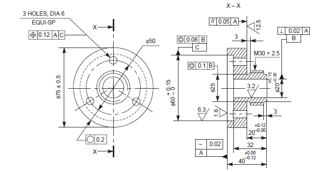 |
| Figure 2- Production Drawing |
Assembly drawing includes all the connecting parts in one single drawing.All parts must their correct working positions and drawing also includes a material box. Material box provide an information for different materials of different parts and number of quantity of that particular part.
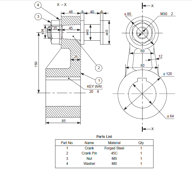 |
| Figure 3- Assembly Drawing |
Exploded assembly drawing has exploded pictorial views are supplied to meet instruction manual requirements.
These drawings generally find a place in the parts list section of a company instruction manual. experience in the reading of drawings; because in these exploded views, the parts are positioned in the sequence of assembly, but separated from each other.
 |
| Figure-4 Exploded assembly view |
Title Block
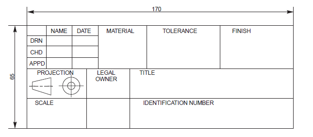
Title block included in the lower right portion of the drawiung sheet. Maximum length of the title block is 170mm and ti includes following
informations
- Title of the drawing
- Sheet number
- Scale
- Symbol of projection
- Name of firm
- Initial of staff drawn, checked and approved
According to Bureau of Indian Standards, SP-46:1998, ‘‘Engineering Drawing Practice
for Schools and Colleges’’, First angle projection is preferred
 |
| Figure-5 Title block |
Drawing sheet layout is as follows
 |
| Figure 6-Drawing sheet laout |
Four centering marks may be provided, in order to facilitate positioning of the drawing. Two orientation mark may be provided to indicate the orientation of the drawing sheet on the drawing board.
It is recommended to provide a figure-less metric reference graduation, with a minimum length
of 100 mm and divided into 10 intervals on all the drawing sheets which are intended
to be microfilmed. The metric reference graduation may be disposed symmetrically about a
centering mark, near the frame at the border, with a minimum width of 5 mm
Scale
Scale is the ratio of the linear dimension of an element of an object as represented in the
drawing, to the real linear dimension of the same element of the object itself. Wherever possible,
it is desirable to make full size drawings, so as to represent true shapes and sizes. If this is not
practicable, the largest possible scale should be used. While drawing very small objects, such
as watch components and other similar objects, it is advisable to use enlarging scales.
SCALE 1 : 1 for full size,
SCALE × : 1 for enlarged scales,
SCALE 1 : × for reduced scales
Lines
Lines of different types and thicknesses are used for graphical representation of objects.
 |
| Figure 7-Types of lines |
Application of lines
Above lines are used in drawing as indicated in following figure
  |
| Figure-8 Applications of lines |
Order of priority of coincided lines
When two or more lines are coincided than it is important task for engineer to give priority of drawing lines- Visible outline and edges
- Hidden outline and edges
- Cutting planes
- Center lines and line of symmetry
- centroid lines
- Projection lines

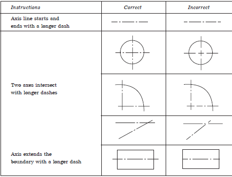 |
| Figure-9 Order of priority of lines
Conventional representation of materials
Engineeering drawing include so many different types of materials and for reading the engineeniring drawing, wee must have different representation of these materials. Steel, metals, wood, liquid, concrete etc. have its special symbols of representations
|
 |
| Figure-10 Conventional representation of materials |
When drawing include repetition of same thing than it is advised to make conventional representation of the drawing. This way may save time of drawing. Some examples are as follows


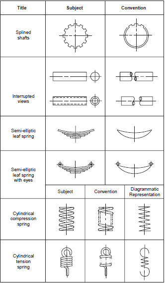 |
| Figure 11- Conventional representation of machine component |
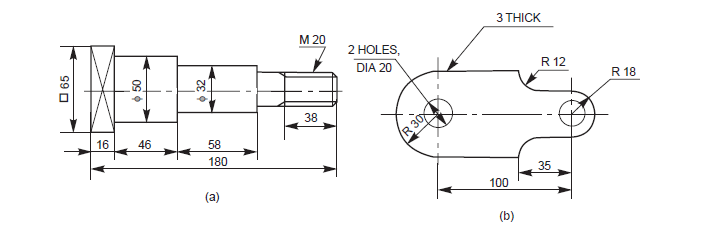
Dimension Principles
Drawing is finished after providing a proper dimensions in a specific unit system. It helps engineer to read the drawing. It represented by numeric value by thin lines, symbols etc.
- As far as possible, dimensions should be placed outside from the drawing
- Dimension should be taken from visible outline rather than invisible outline
- Dimensioning of center line should be avoided except when the center line passes from center of the hole
- Each feature should dimensioned once only in the drawing
- Dimension should be placed on the view or section that relates to the corresponding feature
- Each drawing should use same unit for all dimensions
- No more dimensions than are necessary to define a part
- No feature of a part should be defined by more than one dimension in any one direction
Orthographic view
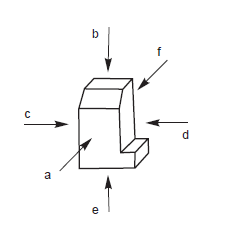 |
| Figure 12- Orthographic view |
 |
| Figure 13- (a) First angle (b) Third angle |
Applications of hidden lines
While make drawing of some component and make projection of it may seen that some parts are not visible. For representation of these parts, hidden lines are used.
While make drawing of some component and make projection of it may seen that some parts are not visible. For representation of these parts, hidden lines are used.
 |
| Figure-14 Hidden lines
|
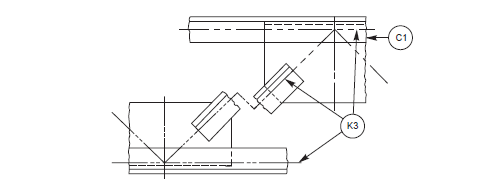
Difficulty in representing the surface can be overcome by following some rules. Whenever the tangential line of curved surface becomes in the projector, a line should be drawn from adjacent view.
 |
| Figure -15 Curved surfaces |
One view drawing
Some machine components are symmetrical about two axis and than we only require one view of this type of component and we can easily drawn a 3D component by using this drawing
 |
| Figure-16 One view drawing |
Section view is representation of cut component in drawing. A section line indicates that object cut portion and view of cut component may be sheen in following example

 |
| Figure-17 Section view representation |
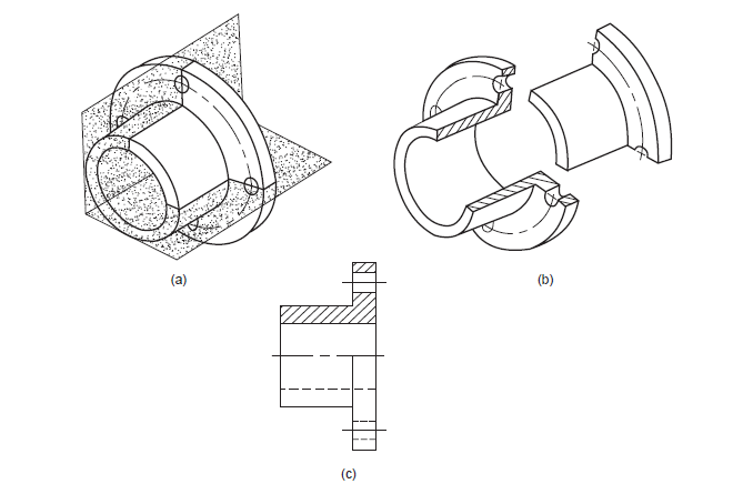 |
| Figure -18 Half section view representation
|
thanks for reading this. I hope you people learn something from this and may be useful for drafting techniques in industrial areas........thanks again....
Contact:
www.andromedacad@gmail.com
+91 8758951337
learn Basics of Engineering Drawing online at virtulearn
ReplyDelete
ReplyDeleteFluorescence Microscope